


MODEL “190LSE”
Line Shaft Live Roller Photo Eye Controlled Accumulator
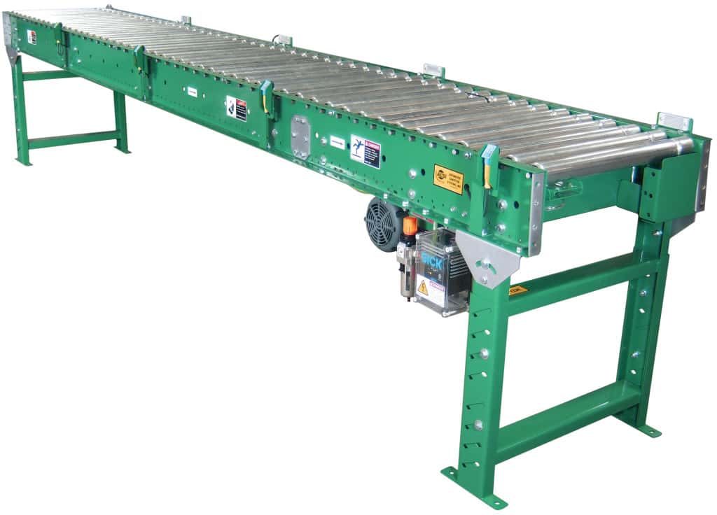
Applications / Features:
- Zero Pressure Accumulation
- Clean Room Installation
- Easy Installation
- True Product Singulation
- No Mechanical Sensor Rollers
- Photo Eye Controlled
Online Resources:
STANDARD SPECIFICATIONS
Driving Belts– 3⁄16″ diameter round urethane “O” rings from drive shaft to tread rollers.
Bed– 7″ x 1-1⁄2″ x 12 gauge powder painted formed steel channel frame with heavy duty cross braces and splice plates.
Rollers – 1.9″ diameter x 16 gauge galvanized steel tread rollers with 7⁄16″ hex shaft and sealed, greased for life bearings, spaced on 3″ centers.
Sensing Device – NEMA 1 photoelectric sensor in each zone detects presence of product and activates accumulation feature in the trailing zone if upstream zone is occupied.
Power Supply – 120 VAC power supply controls accumulation feature with 24 VDC output. Power supply will control 50 accumulation zones.
Air Requirements – 20 to 35 psi recommended operating pressure with free air consumption of .0062 cu. ft. per sensor operation.
Accumulation Zones– 24″, 30″, or 36″ long, air operated. Conveyor frame length changes with zone lengths. Note: Zone length must be evenly divisible by roller centers.
Filter/Regulator– Supplied loose for mounting to conveyor side frame, with 3⁄8″ NPT ports.
Guard Rails – 1-1⁄2″ x 1-1⁄2″ x 12 guage galvanized guard rails – both sides. NOTE: Product contact with guard rails will affect product flow.
Floor Supports– Adjustable 31-1⁄2″ to 45-1⁄2″ from floor to top of tread roller.
One support supplied at each end of conveyor and at each bed joint.
Drive – 2 foot module with motor and reducer. Drive module will be bolted to intermediate section.
Drive Shaft – 1″ diameter steel shaft, driven by motor and reducer, runs full length of conveyor. Chain coupling supplied at bed joints to couple sections together.
Drive Spools – Delrin spools located on drive shaft supplies driving power to tread rollers.
Drive Shaft Bearings – Sealed, pre lubricated, self-aligning, precision ball bearings on drive shaft.
Speed Reducer – C-Face mounted heavy duty worm gear reducer.
Motor -1⁄2 HP 230/460/3-60 TE motor.
Drive Guard– Expanded metal guard full length of conveyor covers drive shaft and other moving drive components.
Conveying Speed – 60 FPM constant.
Capacity– 15 lbs. per tread roller maximum. Not to exceed Load Capacity Chart.
(For Optional Equipment, Weight Specifications, and Engineering Line Drawings, please see catalog pages, above).
(Optional colors available at extra cost)
OPTIONAL EQUIPMENT
Conveying Speed – Constant and variable speeds from 30 to 120 FPM available.
Timing Belt Drive – For speeds 90 FPM and above a timing belt drive in lieu of #50 chain drive is recommended.
Roller Centers – 2-1⁄4”, 4”, 6”, or 8” centers. NOTE: Capacities change as roller centers change. See engineering section of price list for capacity changes.
Accumulation Zones – 18”long, air operated. Conveyor frame lengths change with zone lengths. NOTE: Zone length must be evenly divisible by roller centers.
Floor Supports – Lower or higher supports available. Minimum elevation with standard drive mounting is 18″ from floor to top of rollers.
Powered Right Angle Belt Transfer – Air operated pop-up round belt transfer mounted in 32″ long modular section, 75 lbs. maximum unit load.- Reversing UBT is 39″ long.
Package Stops – Manual or air operated, blade or roller stops available.
Slug Release – Allows for conveyor to be quickly unloaded when accumulation feature is not required.
Motor – Single phase, energy efficient, explosion proof, etc. Other HP available.
Ceiling Hangers – 1⁄2″ diameter threaded rods 8 feet long with locking nuts and mounting hardware.
Jump Chain – One-to-one chain drive moves drive shaft to opposite side for driving various optional accessories.
MODEL “190LS”
Line Shaft Live Roller Accumulator
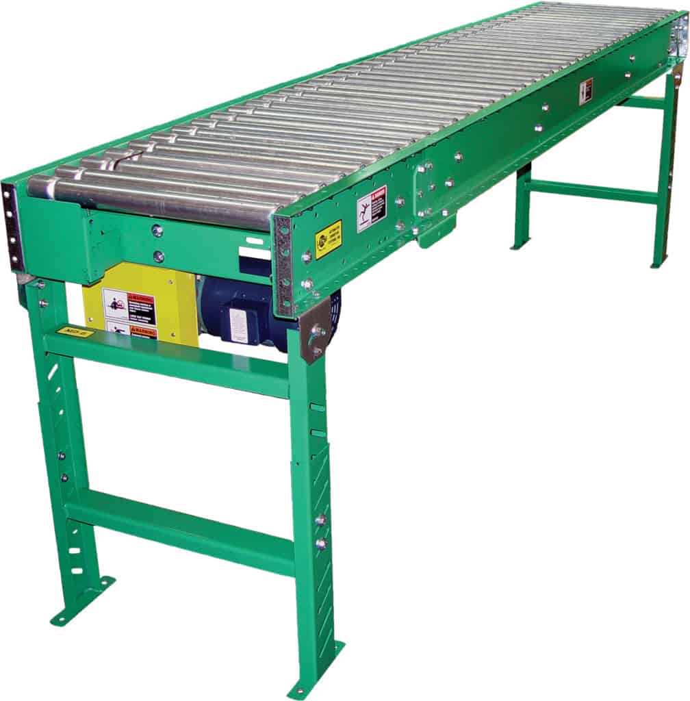
Applications / Features:
- Low Pressure Accumulation
- Clean Room Installation
- Economical Transportation Conveyor
- Assembly Conveyor
Online Resources:
STANDARD SPECIFICATIONS
Driving Belts – 3⁄16″ diameter round urethane “O” rings from drive shaft to tread rollers.
Bed – 7″ x 1-1⁄2″ x 12 gauge powder painted formed steel channel frame with heavy duty cross braces and splice plates.
Rollers – 1.9″ diameter x 16 gauge galvanized steel tread rollers with 7⁄16″ hex shaft and sealed, greased for life bearings, spaced on 3″ centers.
Floor Supports – Adjustable 31-1⁄2″ to 45-1⁄2″ from floor to top of tread roller. One support supplied at each end of conveyor and at each bed joint.
Drive – 2 foot module with motor and reducer. Drive module will be bolted to intermediate section.
Drive Shaft – 1″ diameter steel shaft, driven by motor and reducer, runs full length of conveyor. Chain coupling supplied at bed joints to couple sections together.
Drive Spools– Delrin spools located on drive shaft supplies driving power to tread rollers.
Drive Shaft Bearings – Sealed, prelubricated, self aligning, precision ball bearings on drive shaft.
Speed Reducer– C-Face mounted, heavy duty worm gear reducer.
Motor– 1⁄2 HP 230/460/3-60 TE motor.
Drive Guard– Perforated metal guard full length of conveyor covers drive shaft and other moving drive components.
Conveying Speed – 60 FPM constant.
Capacity– 15 lbs. per tread roller maximum. Not to exceed Load Capacity Chart.
(Optional colors available at extra cost)
OPTIONAL EQUIPMENT
Conveying Speed – Constant and variable speeds from 30 to 120 FPM available.
Timing Belt Drive– For speeds over 90 FPM a timing belt drive in lieu of #50 chain drive is recommended.
Roller Centers-Tread rollers can be placed on 2-1⁄4″, 4″, 6″, or 8″ centers. NOTE: Capacities change as roller centers change. See engineering section of price list for capacity changes.
Floor Supports– Lower or higher supports available. Minimum elevation with standard drive mounting is 18″ from floor to top of rollers.
Powered Right Angle Belt Transfer– Air operated pop-up round belt transfer mounted in 32″ long modular section, 75 lbs. maximum unit load.
Package Stops – Manual or air operated blade or roller stops available.
Guard Rails-Adjustable channel or solid fixed guard rails available.
Motor – Single phase, energy efficient, explosion proof, etc. Other HP available.
Ceiling Hangers – 1⁄2″ diameter threaded rods 8 feet long with locking nuts and mounting hardware.
Jump Chain-One-to-one chain drive moves drive shaft to opposite side for driving various optional accessories.
MODEL “190LSC / 190LSCS / 190LSS”
Line Shaft Live Roller
Curves and Spurs
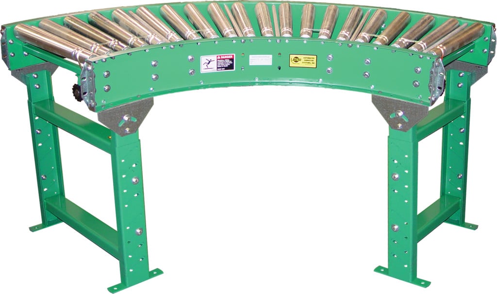
Applications / Features:
- 5 Bed Widths
- Slave Driven from Model “190LS”
- High Speed Capabilities
Online Resources:
STANDARD SPECIFICATIONS
Bed – Roller bed with 2-1⁄2″ diameter tapered to 1-11⁄16″ diameter x 14 gauge galvanized and 1.9″ diameter x 16 gauge galvanized tread rollers. Mounted in 7″ x 12 gauge powder painted formed steel channel frame.
Floor Supports– Adjustable 31-1⁄2″ to 45-1⁄2″ from floor to top of rollers. One support at ends of 190LSC (Curve), 190LSCS (Curve Spur) and 190LSS (Straight Spur). Single leg supplied for center of outside rail on 90° 190LSC only.
Slave Driven– Curves or spurs are slave driven from drive shaft of Model 190LS conveyor. Shafts are coupled by chain coupling at bed joints.
Drive Shaft– 1″ diameter steel shaft extends full length of conveyor, coupled with universal joints (“U” joints) at necessary intervals.
Drive Spools – 2″ diameter Delrin spool held in place on drive shaft with “snap-on” lock collars.
Drive Guard– Underside of drive shaft with spools and drive belts guarded full length of conveyor.
Drive Belts – 3⁄16″ diameter urethane belt from drive spool to tread roller.
Bearings – Tread rollers, pre-lubricated ball bearings. Sealed, pre-lubricated, self-aligning ball bearings on drive shaft.
Butt Couplings– Standard for connecting to 190LS.
Capacity– See Load Capacity Chart.
(For Optional Equipment, Weight Specifications, and Engineering Line Drawings, please see catalog pages, above).
(Optional colors available at extra cost)
OPTIONAL EQUIPMENT
Conveying Speed – Other constant and variable speeds from 30 to 120 FPM.
Guard Rails – Adjustable channel, continuous channel,steel guard rails available.
Floor Supports – Lower or higher supports available. Minimum elevation with standard drive mounting is 18″ to top of rollers.
Ceiling Hangers – 1 ⁄2″ diameter x 8’0″ long threaded rods with locking nuts and mounting hardware.

