


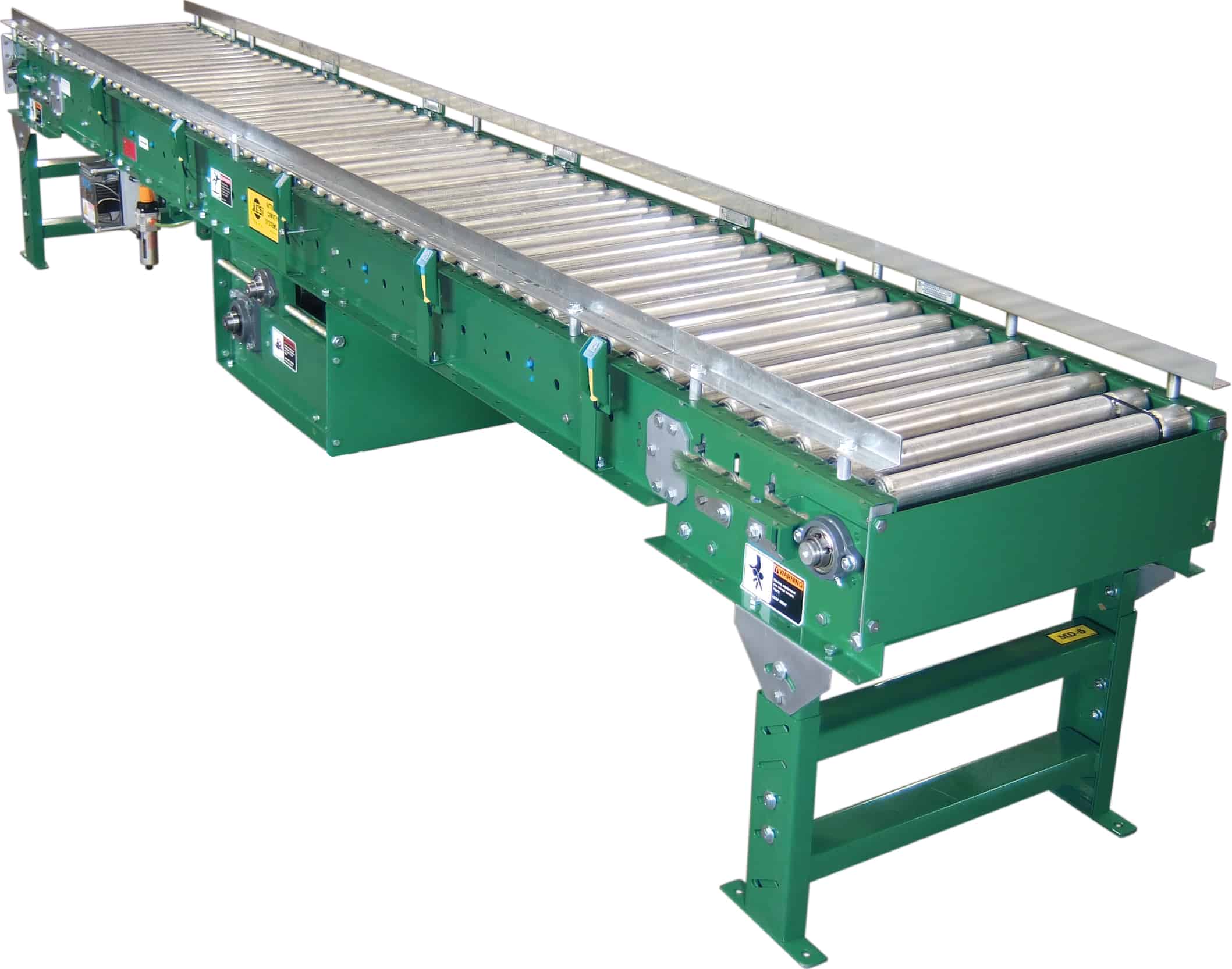
MODEL “190ABE”
Medium Duty Zero Pressure Photo Eye Controlled Accumulator
Applications / Features:
- Zero Pressure Accumulation
- Air Operated Zones
- Easy Installation
- Economical
- No Mechanical Sensor Rollers
- Photo Eye Controlled
Online Resources:
STANDARD SPECIFICATIONS
Driving Belt – Black PVC 120 belt.
Bed – Roller bed width between frames, 15″, 21″, 27″, 33″, and 39″. 7″ x 1-1/2″ x 12 gauge powder painted formed steel channel frame, bolted together with butt couplings and floor supports. Frame sections are 10′ 0″ and 5′ 0″ long.
Tread Rollers – 1.9″ diameter x 16 gauge galvanized steel rollers spaced on 3″ or 6″ centers. Safety pop-out design prevents damage to product or harm to personnel if caught between belt and tread rollers.
Pressure Rollers– 1.9″ diameter x 16 gauge galvanized steel rollers with 7/16″ hex shaft spaced on 6″ and 12″ centers. Raised by air to drive tread rollers, lowered when sensing device is activated.
Sensing Device– NEMA 1 photoelectric sensor in each zone detects presence of product and activates accumulating feature in the trailing zone if upstream zone is occupied.
Power Supply – 120 VAC power supply controls accumulation feature with 24 VDC output.
Power supply will control 50 accumulation zones.
Air Requirements – Operating pressure is 20-35 psi on main trunk line.
Accumulation Zones – 24″, 30″, or 36″ long, air operated. Conveyor frame lengths change with zone lengths. NOTE: Zone length must be evenly divisible by roller centers.
Filter/Regulator – Supplied loose for mounting to conveyor side frame, with 3/8″ NPT ports.
35 to 40 psi recommended operating pressure with free air consumption of .0062 cu. ft. per sensor operation.
Guard Rails – 1-1/2″ x 1-1/2″ x 12 gauge galvanized angle guard rails, both sides.
NOTE: Product contact with guard rails will affect product flow.
Tail Pulley – 4″ diameter crowned with 1-3/16″ shaft.
Drive Pulley – 8″ diameter crowned and fully lagged with 1-7/16″ diameter shaft. Located at infeed end of conveyor.
Snub Roller – 2-1/2″ diameter adjustable, located directly behind drive pulley. 2″ diameter at each end directly behind terminal pulleys
Return Idlers – 1.9″ diameter adjustable on 10’0″ centers.
Floor Supports – 31-1/2″ to 45-1/2″ adjustable from floor to top of rollers. One support supplied at each end of conveyor and at each bed joint.
Take-Up – Screw type take-up located at end of conveyor to maintain belt tension.
12″ of belt take-up provided.
Bearings – Sealed and pre-lubricated with cast iron housings.
Speed Reducer – C-Face mounted heavy duty worm gear reducer.
Motor – 1/2 HP 230/460-3-60 TE motor.
Conveyor Speed – 60 FPM constant. Some higher and lower speeds available. However, most efficient accumulation occurs at 60 FPM.
Capacity – 150 pounds per foot max. unit load. Not to exceed Load Capacity Chart (see catalog page).
(For Optional Equipment, Weight Specifications, and Engineering Line Drawings, please see catalog pages,
(Optional colors available at extra cost)
OPTIONAL EQUIPMENT
Center Drive – Mounted below conveyor bed section.Can be placed most anywhere in conveyor length.
Floor Supports – Higher or lower supports available. Minimum elevation with standard end drive, 25″.
Accumulation Zones – 18” long, air operated. Note: Zone length must be evenly divisible by roller centers.
Roller Brakes – (4) per zone.
SlugRelease – Allows for conveyor to be unloaded quickly when accumulation feature not required.
Ceiling Hangers-1/2″ diameter thread rods 8’0″ long with locking nuts and mounting hardware. Other lengths are available.
Air Control Zone Stop – Pneumatic brake to stop rollers in work station area.
Motor- Single phase,energy efficient,explosion proof,etc. Other HP available. Electrical Controls – Magnetic starters and push button stations; manual motor starters with overload protection,others.
OPERATIONAL SEQUENCE
1) Model” 190LSE” is loaded at the infeed end of conveyor. The first load travels the entire length of conveyor to Zone #1. If the photoelectric sensor in Zone #1 has been activated by an external signal (normally open contact, not supplied) the product will stop in Zone #1.
2) The second load travels the length of conveyor until reaches Zone #2. If zone #1 is occupied, the second load will stop in zone #2. Load #3 will stop in Zone #3 and continue to accumulate at “zero pressure” until fully loaded.
3) To unload, an external signal (normally open contact, not supplied) to the photoelectric sensor in Zone #1 will release the accumulation feature and allow the product in zone #1 to leave the conveyor. The load in zone #2 will not advance into #1 until the load Zone #1 has completely cleared Zone #1’s photoelectric sensor; the third load will not advance into Zone #2 until the second load clears the photoelectric sensor in Zone #2. Once the first load clears the photoelectric sensor in zone #1, the external signal must be restored to Zone #1’s photoelectric sensor for the accumulation process to continue.

